NEMA Wiring Schematic Guide for Electrical Specialists
Approximately seventy percent of electrical failures within establishments result from inadequate wiring methods. Such data emphasizes the requirement of following set protocols, spotlighting NEMA wiring schematics’ importance for electrical specialists. By means of these schematics, wiring configurations that meet both performance productivity and highest security norms are delineated.
The objective of this guide is to equip electrical professionals with deep insights into NEMA standards. Highlighting the importance of correct electrical installations is crucial. By mastering these principles, specialists can significantly minimize the risk of hazards and confirm they adhere to safety measures endorsed by Installation Parts Supply. Understanding of l14-30 plug wiring diagram is crucial whether creating modern networks or repairing current ones, as it boosts the capacity to offer safe and trustworthy electrical answers.
Vital Takeaways
- NEMA wiring schematics are vital for guaranteeing electrical safety and adherence.
- Correct wiring techniques can decrease electrical issues significantly.
- Comprehending NEMA criteria improves the performance of electrical installations.
- Installation Parts Supply promotes compliance with safety protocols in electrical tasks.
- NEMA schematics support a wide range of applications across multiple industries.
Understanding NEMA Norms and Why They Matter
NEMA standards are crucial in the electrical field, directing security and operation meticulously. Developed by the National Electrical Manufacturers Association, they establish critical benchmarks for designing, testing, and identifying electrical appliances. Such measures guarantee uniformity and reliability across all electrical configurations, which is of great value.
What Are NEMA Norms?
NEMA classifications span from classes 1 to 13. Every level delineates the conditions necessary for electrical devices to function efficiently. For example, NEMA 1 delivers basic indoor protection but does not offer dust shielding. Conversely, NEMA 4 guarantees appliances is waterproof, a must for surviving significant water immersion. Understanding these designations is key in choosing suitable devices.
Why NEMA Norms Are Important for Electrical Safety
The function of NEMA criteria in maintaining electrical safety is substantial. They play a significant part in reducing electric shock, apparatus breakdowns, and burn risks. Correct adherence to NEMA ratings empowers devices to function safely under particular surrounding conditions. For external application, NEMA 3 standards deliver protection against the elements, safeguarding the apparatus from harsh climate like precipitation and snow. In zones susceptible to explosions, standards including NEMA 7, 8, and 9 are essential for ensuring safety.
Uses of NEMA Criteria in Wiring Schematics
The application of NEMA standards in wiring drawings is crucial for protected, efficient electrical systems. These schematics utilize uniform symbols and formats derived from NEMA standards, simplifying the interpretation of detailed electrical configurations. Such standardization is advantageous. It promotes transparency, consistency, and minimizes confusions, and thereby boosting electrical safety across home and commercial environments.
NEMA Wiring Diagram Basics
NEMA wiring diagrams are crucial for electrical professionals, rendering complex junctions transparent. They describe the junctions and components in diverse installations. By grasping the components, kinds, and notations of NEMA schematics, professionals can enhance their performance in setups and servicing.
Constituents of NEMA Wiring Drawings
NEMA drawings include key components for distinct electrical installations. You’ll find wiring terminals, couplers, and other equipment for reliable connections. Each piece secures energy is allocated optimally, in accordance with safety guidelines.
Categories of NEMA Wiring Drawings
NEMA utilizes multiple schematics, like connection diagrams and electrical designs. Such diagrams depict appliance interconnections, while arrangements illustrate current flow. Opting for the right drawing aids in problem solving and installation.
Common Icons Used in NEMA Wiring Diagrams
Symbols in wiring diagrams are crucial for clear clarity. They illustrate switches, circuits, and couplers. Recognizing these notations helps teams read diagrams properly. Such practice ensures configurations meet NEMA norms.
NEMA Wiring Diagram Attributes
For electrical professionals, grasping the core elements of accurate electrical wiring schematics is essential. These drawings bring both transparency and wholeness, synchronizing configurations with NEMA norms. They demand accurate marking and proportioning to minimize installation errors. This encourages a more secure and optimal working environment.
Key Features of Correct Electrical Wiring Diagrams
Accurate electrical wiring drawings are vital in electrical initiatives. They incorporate crucial qualities such as:
- Lucidity: Schematics must be simple, minimizing misinterpretation risks.
- Wholeness: They need to contain all vital parts, junctions, and electrical standards.
- Conformance: Complying with NEMA norms is imperative for ensuring protection and performance.
- Comprehensive Marking: Distinct markings on each component are crucial for grasping and avoiding mistakes.
- Correct Scaling: The dimensions should mirror the actual setup to depict the arrangement accurately.
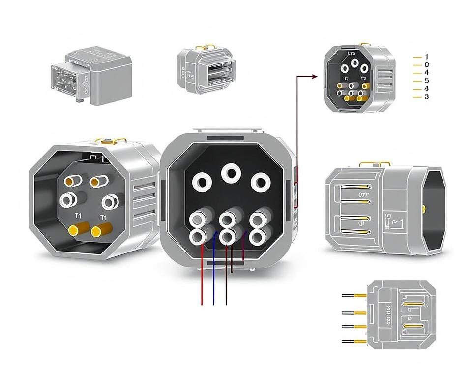
Grasping NEMA Coupler Configuration
The insight into NEMA coupler configuration is critical for forming proper linkages in electrical setups. Knowledge about distinct pin configurations maintains security and device functionality. There exists a range of NEMA interfaces, designed for different voltages and currents, including:
| Connector Model | Ampere Rating | Voltage Level |
|---|---|---|
| L5-15 | 15A | 125V |
| L5-20 | 20A | 125V |
| L14-20 | 20A | 125/250V |
| L1430C | 30A | 125/250V |
| L620C | 20A | 250V |
| L1430C | 30A | 125/250V |
| L630R | 30A | 250V |
Grasping NEMA connector configurations is vital for stable junctions, boosting effectiveness. It’s imperative to pair couplers with devices correctly using locking or straight blade types, to dodge dangers.
NEMA Device Wiring
NEMA device wiring covers multiple configurations for secure electrical device interfaces. These guidelines confirm that appliances work together safely, reducing risk. Grasping the diverse NEMA appliances and their wiring is essential for technicians.
Various Kinds of NEMA Units
NEMA categorizes appliances by kind based on voltage and amperage requirements. Primary setups are:
- 2-Pole, 2-Wire
- 2-Pole 3-Wire Grounding
- 3-Pole, 3-Wire
- 3-Pole, 4-Wire with Grounding
- 4-Pole 4-Wire
- 4-Pole 5-Wire Grounding
These setups are utilized in homes and factories, supporting 125V, 208V, and 480V.
NEMA Outlet Wiring Outlined
NEMA plug wiring changes to meet multiple power needs, with twist-lock types ensuring reliable junctions in vibrating conditions. Such as, the L5-15 plug works at 15 A, typical of enterprise settings, whereas the L14-20 is crafted for 20 A at 125/250 volts.
The NEMA naming scheme helps in selecting the appropriate plugs, spotlighting characteristics like charge orientation and earthing. This precision ensures that appliances perform reliably.
NEMA Outlet Wiring Instructions
Correct wiring of NEMA receptacles meets electrical codes and safety guidelines. For example, L530R receptacles are configured for 30 amps at 125 volts, with L630R options for 250 volts. Correct grounding is essential to avoid electrical mishaps.
Opting for accredited NEMA plugs and receptacles ensures protected, standard-compliant setups. It’s vital to check formal protocols when setting up.
NEMA Motor Wiring and Implementations
NEMA motor wiring is essential in electrical design, particularly for manufacturing use. Knowing how NEMA motor configuration works ensures that machines are integrated for peak operation. Motors, like one-phase and three-phase models, require correct wiring to work safely and optimally.
Summary of NEMA Motor Wiring
Comprehending NEMA motor wiring requires familiarity of junctions and setups. Most three-phase motors now support dual-voltage, signifying they can operate at both low (208-230V) and high power levels (460V). Wiring at high voltage results in lower current draw than at low voltage. High voltage advantages include thinner cables for the input, a notable benefit for engines over 10 HP.
While both NEMA and IEC units are utilized in the sector, NEMA versions are typically larger and more costly than IEC ones for under 100 HP deployments. NEMA starters range from size 00 to 9, appropriate for various uses. A standard feature in NEMA trips is a Fault Class of 20, engineered to activate when a motor’s draw exceeds 6-fold the rated current in 10 secs.
Selecting the Appropriate NEMA Motor Setup
Choosing the appropriate NEMA motor setup affects system performance and protection. A standard three-wire control circuit uses three wires for a start/stop pushbutton interface, facilitating straightforward motor management. Common three-phase configurations comprise the 12 Lead Dual Voltage and 6 Lead, enabling Wye and Delta arrangements.
IEC motor starters frequently incorporate phase failure detection, boosting safety. They also offer modifiable Trip Classes for tailored protection in low voltage levels operations. Additionally, many variants have thermal protection, critical for single-phase and Dual Voltage systems.
| Configuration Type | Voltage Level | Current Specification | Usual Function |
|---|---|---|---|
| 12 Lead Dual Voltage | Dual Voltage (208-230V / 460V) | Varies by motor size | Wye Start and Delta Run setups |
| 6 Lead | Single/Dual Voltage | Maximum 32A | Wye or Delta connections |
| Single Phase | Single-level Voltage | Dependent on adjustment (1-5A) | Applications with Two Speed, Two Winding |
| Delta Connection | Elevated Voltage | Based on configuration | Various applications including Current Transformers |
The Bottom Line
Understanding NEMA wiring diagrams and norms is crucial for electrical experts aiming to boost their skills and follow electrical security guidelines. These guidelines secure protected and efficient electrical setups but also avert risks associated with improper wiring. As discussed, adhering to NEMA criteria leads to the enhanced capability of diverse NEMA devices and systems.
For electricians, the availability of superior supplies can significantly impact the outcome of their work. Installation Parts Supply presents a wide range of wiring items in accordance with NEMA criteria. This empowers specialists to access essential parts for complying with these significant requirements. Premium supplies and profound knowledge of NEMA wiring diagrams greatly enhance project security and performance.
During electrical deployments, always place safety and exactness first. Mastering NEMA standards offers the knowledge necessary for executing best practices accurately. This ensures that every electrical junction made conforms to premium criteria.
FAQ
Which are NEMA wiring drawings?
NEMA wiring drawings display the configurations and connections of NEMA-standard electrical devices. They adhere to safety and performance criteria defined by the National Electrical Manufacturers Association.
What makes NEMA criteria important for electrical protection?
NEMA criteria are essential to establishing safety and performance criteria for electrical equipment. These guidelines assist electrical experts reduce electric shock, operational errors, and fire hazards.
Identify the key parts are crucial in a NEMA wiring diagram?
Fundamental parts in a NEMA wiring drawing include circuit configurations and connection schematics. These drawings also feature thorough labels and illustrate the electrical system’s diverse parts accurately for installations.
Which kinds of NEMA wiring schematics exist?
Various NEMA wiring schematics address diverse requirements, including energy distribution layouts and connector schematics. Each layout fulfills a distinct role in electrical systems.
Which are the typical symbols found in NEMA wiring schematics?
Common symbols in these schematics represent toggles, interruptors, outlets, and additional components. Utilization of these symbols promotes unambiguous interaction and precise interpretation of wiring diagrams.
Which are the main features of precise electrical wiring drawings?
Correctness in electrical wiring drawings is marked by their clarity, comprehensiveness, and detailed marking. They need to meet NEMA standards to avoid errors in deployment.
Define a NEMA connector configuration?
A NEMA connector layout outlines electrical connections at a connector, displaying specific pin assignments. This guarantees secure and optimal junctions in electrical setups.
Identify the different kinds of NEMA devices?
NEMA appliances consist of various electrical outlets and couplers, like adapters and receptacles. They are designed for diverse ampere and power criteria to satisfy unique operational demands.
How is NEMA plug wiring arranged?
NEMA plug wiring is determined by defined current and voltage levels needs, adhering to safety standards and regulatory standards for multiple electrical uses.
What guidelines are there for NEMA receptacle wiring?
Guidelines for connecting NEMA receptacles underline complying with electrical standards, guaranteeing correct charge alignment, and picking correct wire sizes. This sustains both security and performance in electrical setups.
Describe how to wire a NEMA motor effectively?
To wire a NEMA motor, one must understand its particular one-phase or tri-phase arrangement. Opting for the correct wiring method is vital, plus maintaining electrical safety for maximum motor efficiency.
What must be taken into account when choosing a NEMA motor setup?
Selecting a NEMA motor configuration necessitates an assessment of the project’s voltage and current demands and performance traits. It’s also crucial to verify suitability with pre-existing machinery for assured efficiency and security.